This example can be reproduced with data of patient PFUS1 available in the example PMOD database after installation. Please note that the FCH and FDG PFUS1 series are rigidly matched beforehand to the MRI PFUS1 using the FuseIt module.
These three matched studies are loaded as Input series. The aim is to localize and visualize the brain tumor. A simple yet useful approach to be performed on the Segmentation page is the following:
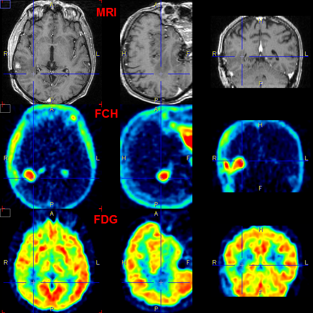
FCH |
The tumor is well delineated in the FCH data but needs a restriction. ▪Set Thresholding segmentation with criterion >=0. ▪Enable Restrict to VOI box and activate Define VOI button. ▪From PMOD database load the VOI Tumor_Choline(MRI_space) . ▪Remove the Contralat VOI. Confirm with OK and click into the Tumor VOI. ▪Activate the Segmentation button ▪Add Segment to the Segments list. ▪Set Segments 3D rendering properties: set Surface as Rendering Type and surface Color to red. ▪Render the SR segment with the Render selected button |
FDG |
The FDG data is used to obtain the outline shape of the brain. ▪First smooth the FDG data with a 6mm Gaussian. Save the smoothed FDG data. ▪Apply a THRESHOLD segmentation to the smoothed FDG study with a value of 7.9. ▪Activate the Segmentation button. ▪Add Segment to the Segments list. ▪Set Segments 3D rendering properties: set Surface as Rendering Type and surface Color to yellow. ▪Render the current segment in append mode by selecting the pushpin and subsequently the Render selected button. ▪Set blended transparency using a value of 0.7. |
MRI |
MRI slices can be included for a better anatomical understanding. ▪On the 3D Rendering page, Input tab select the MRI study. ▪In the object tree select Planes and then activate Orthogonal for the Add planes. The three orthogonal MRI planes are shown. ▪Switch off the y and the x plane for display in the scene. Only axial MRI slice is shown. ▪Select Transparent mode (selection right to z-plane button) ▪Define the location of the plane using the navigator window, pointing at the location of interest. The scene gets updated accordingly. |
The result from a specific viewpoint is shown below.
