The controlled iso-contouring tool serves for the contouring of structures based on a well-defined intensity threshold. The region-growing process can be restricted within an existing VOI, otherwise it will work on the whole image volume.
Contouring without Restriction
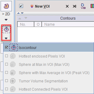
The whole image volume will be processed, if the Isocontour tool ![]() is started without selecting a non-empty VOI in the VOIs list. This situation is given before VOI definitions have started yet, or by creating an empty New VOI.
is started without selecting a non-empty VOI in the VOIs list. This situation is given before VOI definitions have started yet, or by creating an empty New VOI.
The situation below illustrates the initial situation when starting auto-iso on an FDG Brain image: One single Hot contour is shown at a threshold level of 50%. without allowing Inner holes. The procedure operates in 2D and defines the contours in the Z plane, because this plane was active at the time the tool was started.
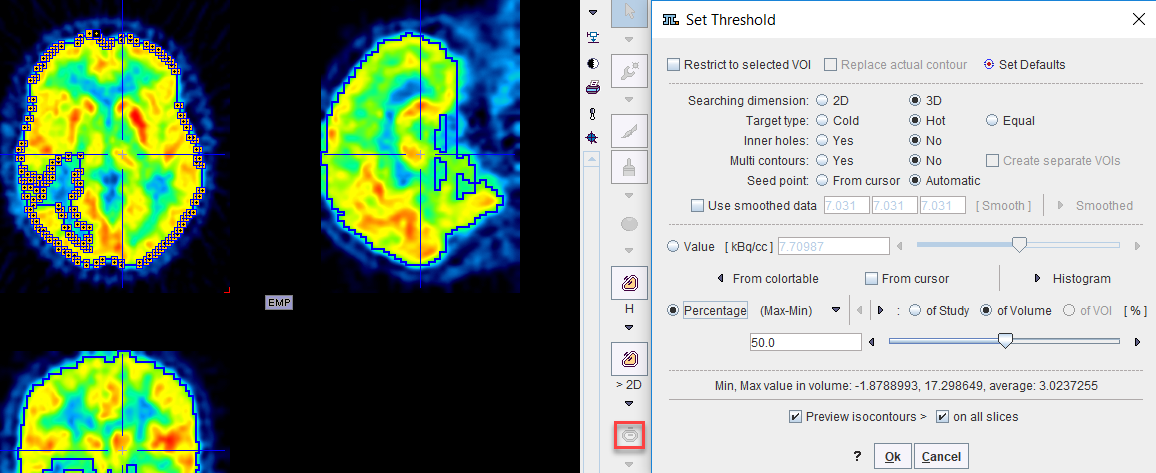
There are various parameters which change the behavior of the algorithm:
▪Threshold options: The user can chose between various types of threshold definitions using the radio boxes. With Value the iso-contouring value should be entered in display units into the threshold number field. With Percentage, the value entered in the threshold field is interpreted as a percentage of the dynamic range (Max-Min) of the whole Study, the current Volume, or the enclosing VOI, respectively. Instead of the Max-Min, the percentage can also be related to the Max only. There are two alternatives to entering the values manually: From colortable copies the value of the lower threshold in the color table. With the From cursor check box enabled, the value is updated with the pixel value whenever one clicks into the image.
▪Searching dimension: 2D processes each slice individually, whereas 3D performs the searching in all 3 dimensions.
▪Target type: Hot (Cold, Equal) is including pixels above (below, equal to) the threshold value, respectively.
▪Inner holes: In the case of Yes, pixels not meeting the criterion which are fully enclosed are removed from the resulting VOI. With No, the VOI will be completely filled.
▪Multi contours: With Yes, the generation of multiple VOIs is allowed. Otherwise, only the largest VOI will be returned.
▪Seed point: Automatic is starting region-growing with the aim to detect structures of maximal volume, whereas From cursor allows starting the search from a manually defined location. In the latter case the From cursor box should also be enabled.
The updated contours are shown in the image, whenever a parameter is changed. For a complete visualization, Preview isocontours on all slices should be enabled. To accept the VOI definition, close the dialog window with the Ok button.
Contouring with Restricting VOI
The process described above can be restricted to the volume of an existing VOI. To do so, select the restricting VOI in the VOIs list, and start the Isocontour tool ![]() and enable Restrict to selected VOI. Regular VOIs are convenient restrictions as the can easily be positioned and scaled. The example below illustrates contouring in a box VOI placed on the left brain hemisphere.
and enable Restrict to selected VOI. Regular VOIs are convenient restrictions as the can easily be positioned and scaled. The example below illustrates contouring in a box VOI placed on the left brain hemisphere.
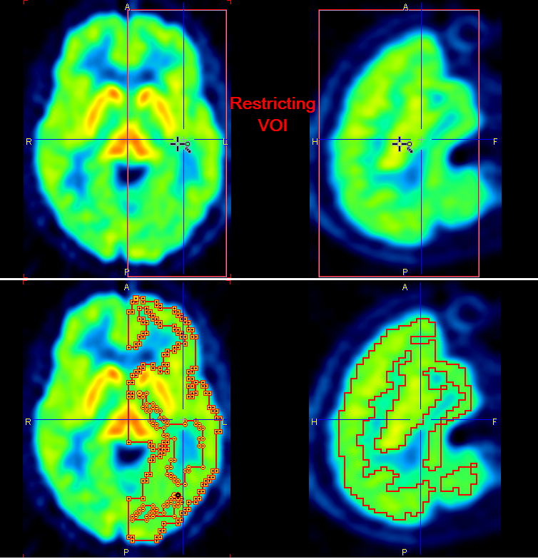
Depending on the setting of Replace actual contour, the bounding VOI will be overwritten, or a new VOI will be created with the contouring result.
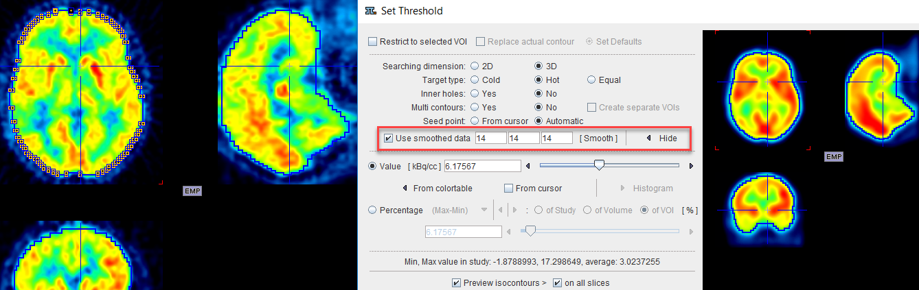
Contouring with Smoothing
In order to get smoother contours than the original data supports, the procedure can work on a smoothed copy of the data. This functionality is activated with the Use smoothed data box.If the Smooth button is activated, the data copy is filtered with a Gaussian function using the three numbers as the FWHM in mm along x, y and z. By adjusting the filter sizes appropriately and repeat filtering, a smooth copy and correspondingly smooth contours in the original image can be generated. The Smoothed/Hide toggle button can be activated to show or hide the smoothed copy.
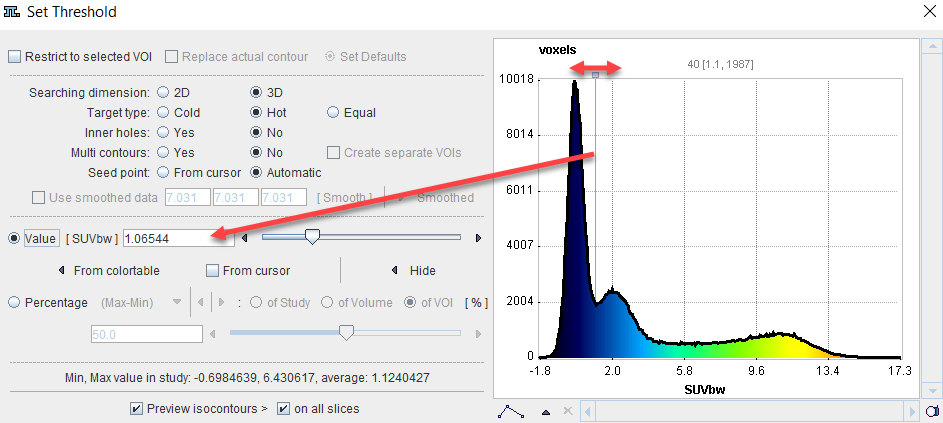
Contouring with Histogram
A histogram can be used to set the threshold Value for the iso-contouring. This functionality is activated with the Histogram button. A histogram of the pixel values is shown, and the value at which the iso-contours are drawn can be adjusted by dragging the marker highlighted in the graphics below. The threshold value is updated each time the marker position is changed and the updated contours are shown in the image. The Hide button collapses the histogram part of the dialog window again.