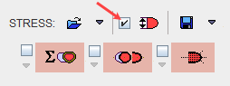
Once the transformation of the study in the standard short axis orientation has been successfully completed, the display shows the MYOCARDIUM images in reslicing mode. With the View model size VOI box enabled as illustrated below:
the green model size VOI is overlaid on the images:
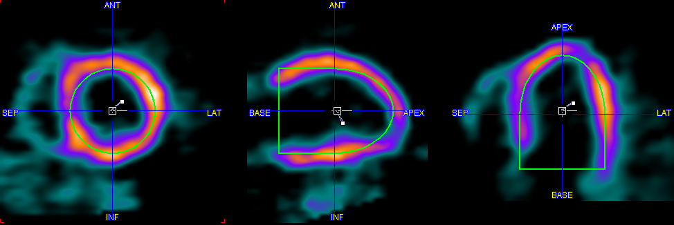
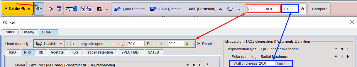
initially, the values of the VOIs model size length and radius are the one defined in the configuration and displayed on the bottom line:
The green model VOI is used to estimate the Myocardium VOI. To modify selectively the model VOI length and radius for the STRESS or REST study activate the dedicated icon e.g. Define model size interactively as illustrated below:
A dialog window appears allowing the interactive model VOI definition:
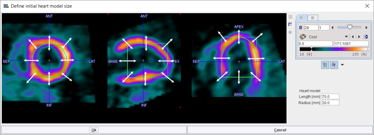
Scale in any direction and plane using the left mouse button with Click+hold+drag. The Heart model Length [mm] and Radius [mm] are updated accordingly. In alternative, the values can be edited in the dedicated text fields. To confirm the new values close the dialog window with the OK button.
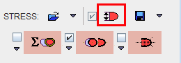
To start the automatic VOI outlining process select the contouring button indicated below

The program tries to find a VOI in the right cavity (RV VOI), in the left cavity (LV VOI), and uses the interactively defined model VOI as the centerline of the myocardium (Myocard VOI).
The box left to the contouring button is for enabling the automatic mode. If it is checked, the contouring process is started as soon as an automatic SA reorientation completes.
The arrow below the box can be used to copy the VOIs from rest to stress, and vice versa. Note that due to subject motion between the studies and different physiologic conditions, the copied VOIs may not be fully adequate and therefore may need adjustments.
Inspecting the Result VOIs
The user is notified if automatic contouring fails. Otherwise, the VOIs resulting from automatic contouring are shown as an overlay in the images. The Epi/Endo definition of the Myocardium consists of two contours. The illustration below explains the different elements in the display.

The green buttons indicate that VOIs have been found for all three structures. It is recommended to check the results before proceeding to the quantification. Crucial locations are:
▪the base: only that part of the base should be included which shows myocardium in the full 360°;
▪the apex: the activity is often reduced towards the apical tip, making the auto-contouring difficult;
▪lesions: the program tries to define a smooth centerline, but gross defects can compromise the results.
The easiest way to check the VOI placement is scrolling through the slices as follows:
1.Select the image presentation tab and adjust the lower/upper thresholds so that the color allows to clearly see the contour lines. Hereby the reslicing mode is also disabled, so that the images are not unintentionally moved.
2.Click into one of the orthogonal images, then scroll through the slices using the mouse wheel.
3.As an alternative click anywhere into the images to get new orthogonal slices at that triangulation point.
If necessary, the VOIs can be adjusted. Use the green buttons open the VOI construction dialog with a corresponding VOI preselected. The VOI definition and correction is explained in the next section.
CAUTION: When scrolling through the slices you will note that the most apical contour essentially consists of a point. Please DO NOT DELETE THIS POINT, because it is essential for the polar plot generation.