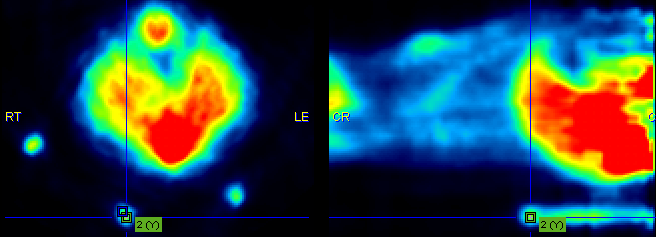
If the automatic matching rigid matching is not working properly for a combination of images, the use of fiducial markers should be considered. In the example below three capillaries filled with activity were attached to the bed of the mouse, and then imaging performed on separate CT and PET systems. The capillaries are clearly visible in the CT, whereas the activity in the inner of the capillaries is picked up by PET. The tubes were plugged by a small plasticine plugs, which can be seen by zooming in on the CT image. Consequently, the end of the capillary activity in PET should correspond to end of the plug in CT.
For marker matching, the user explores the two image sets and marks corresponding locations, i.e. markers. A transformation is then calculated which brings the two spatial arrangements of markers into optimal agreement.
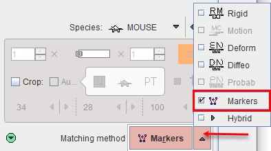
Please first load the input images on the LOAD INPUT IMAGES sub-page and make sure the Species setting is correct. To proceed select the Markers matching as Matching method.
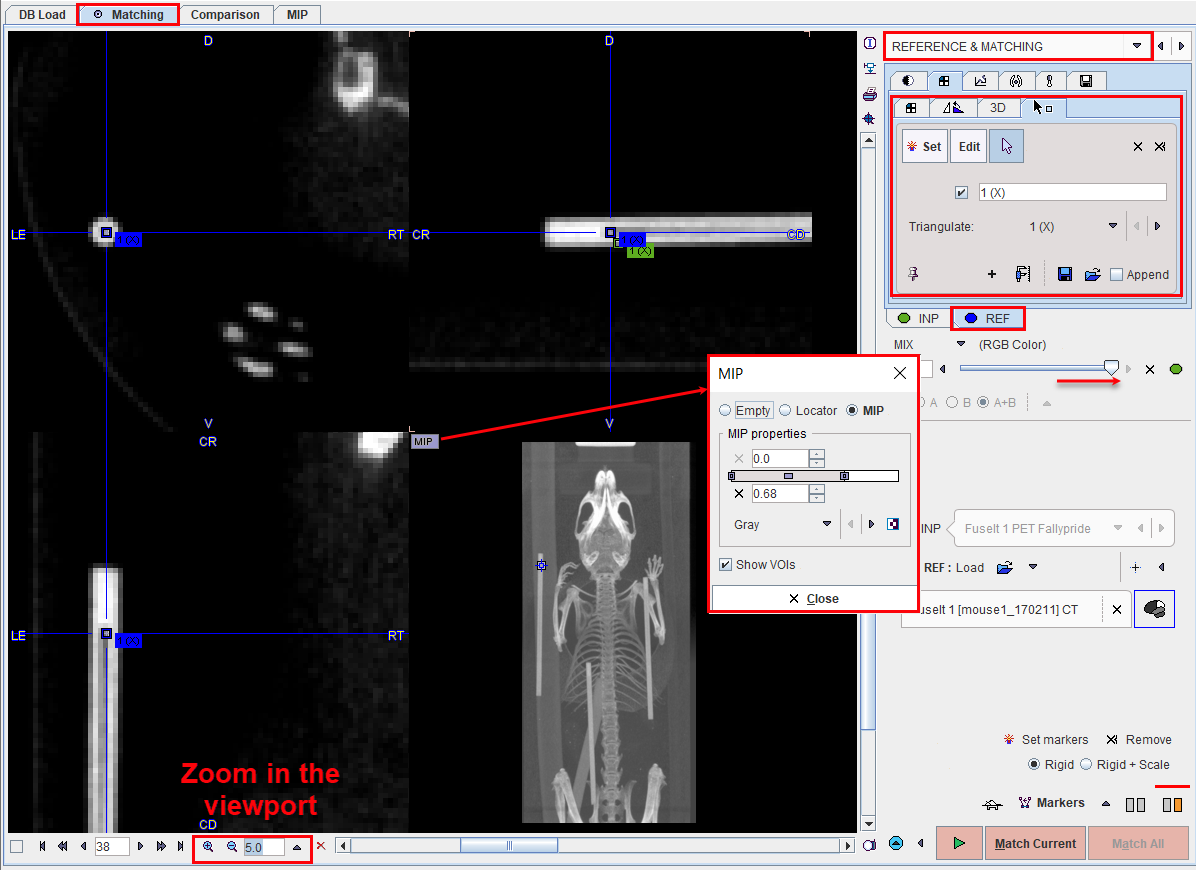
On the REFERENCE &Matching sub-page load the reference image with the REF: Load button. Next start landmark definition with the Set markers button.
Marker Definition for the Reference
1.Shift the fusion slider fully to the right, so that only the REF image is shown.
2.Select the REF panel.
3.Note the panel for markers definition which is already open. The buttons
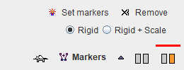
![]() define the behavior when clicking into the image. With Set active, each click into the image generates a marker. With Edit active, markers can be dragged to different locations. The third button is the neutral mode for triangulating the images until the marker position has been found.
define the behavior when clicking into the image. With Set active, each click into the image generates a marker. With Edit active, markers can be dragged to different locations. The third button is the neutral mode for triangulating the images until the marker position has been found.
4.Enable the MIP image in the 4th quadrant with the MIP button indicated above and adjust the color thresholds such that the markers are well visible.
5.Click at the landmark position in the MIP image and then adjust the plane locations by triangulation or plane scrolling (mouse wheel) until the exact position is seen in the images.
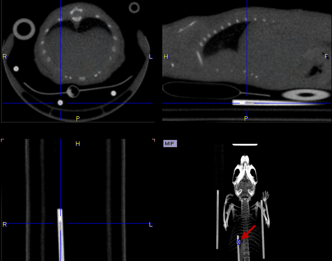
6.Enable the Set mode and click at the landmark position in one of the plane images. A numbered square indicator of the landmark appears
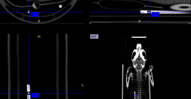
7.Switch back to the neutral mode for triangulating the next landmark position, and then define the second landmark in Set mode.
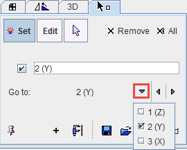
8.It is recommended to repeat landmark definition for more points in order to improve the accuracy. The landmarks can easily be triangulated later by selecting a marker in the Go to list:
Marker Definition for the Input
The next task is the definition of the corresponding landmarks for the input image.
1.Shift the fusion slider fully to the right, so that only the INP image is shown.
2.Select the INP panel.
3.Define the landmarks in the same order as described above.
Matching Parameters
As the image content is not used for the registration, only parameter is whether the transformation is strictly rigid, or whether a scaling is allowed (Rigid + Scale option).
Starting Markers Matching
Please use the Match Current button to start the registration of the two sets of landmarks.