Select the Volume mesh (Polymesh) option in the list and activate the View button to transfer the CFD results to the 3D page. An intermediate dialog window allows selecting the original 4D Flow data:
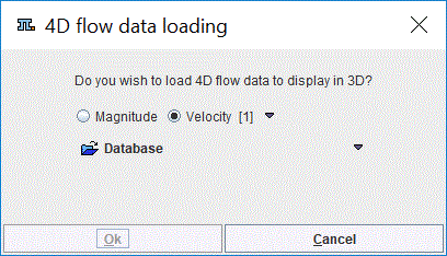
The selected image series may be used for texturing in the 3D interface only if the same data were used to create the geometric model used for the simulation.
The result for a Brain Aneurysm data is illustrated below:
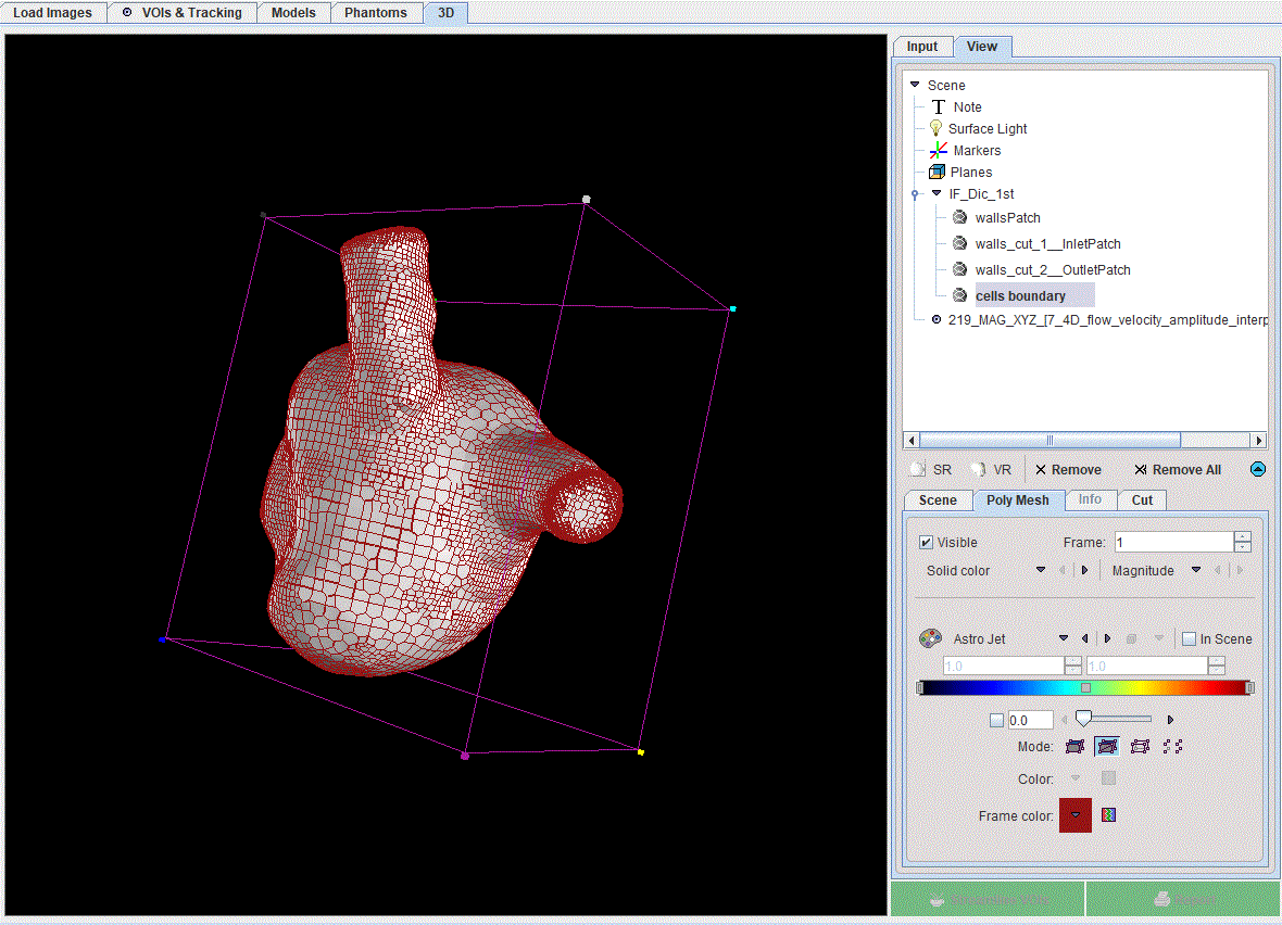
For further visualisation, an oblique cutting plane is applied to the aneurysm CFD results, to reveal internal values for velocity and pressure:
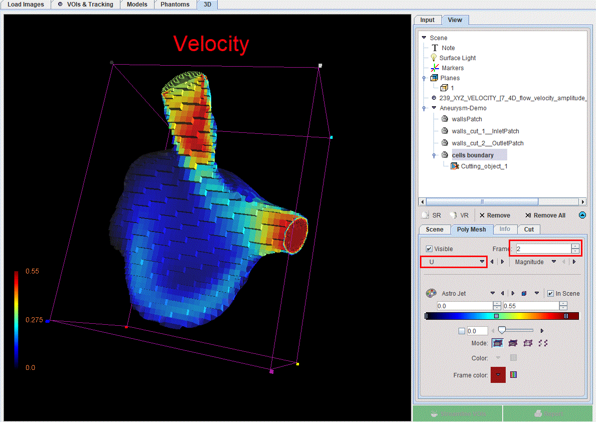
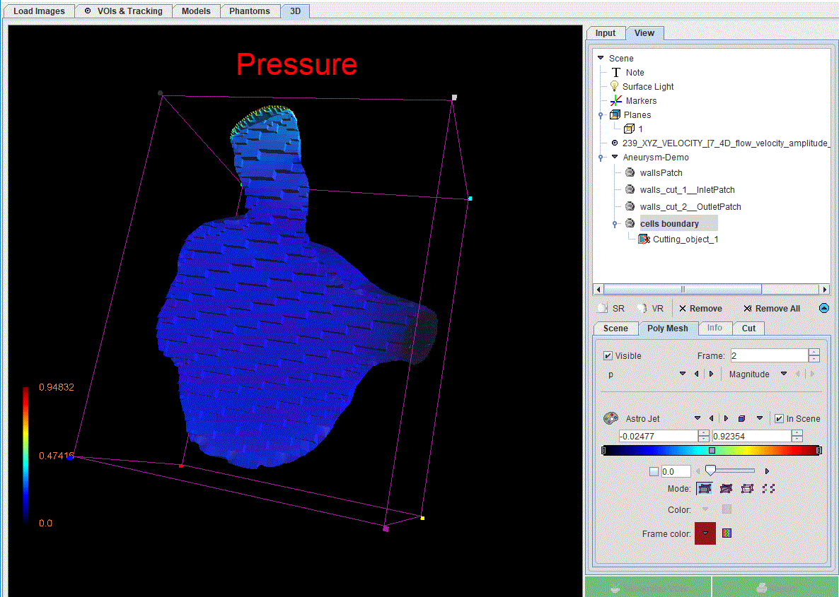
The following settings were used for visualization:
1.All the objects in the View tree were set to Solid.
2.The wallsPatchVisible box was switched OFF.
3.An oblique plane was used to cut the cells_boundary. After cuttin, the plane Visible box was set to OFF.
4.The p (pressure) and the U (velocity) Magnitude selected on Frame 2 were used to texture the cells_bounday object.
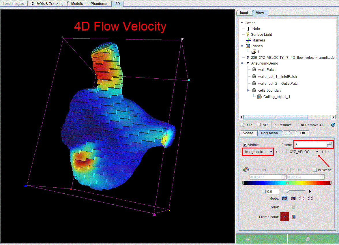
The resulting velocity field and pressure can be compared visually to the known velocity from 4D Flow. To this purpose the loaded Image data with XYZ_velocity selection was overlaid on the cells_boundary object:
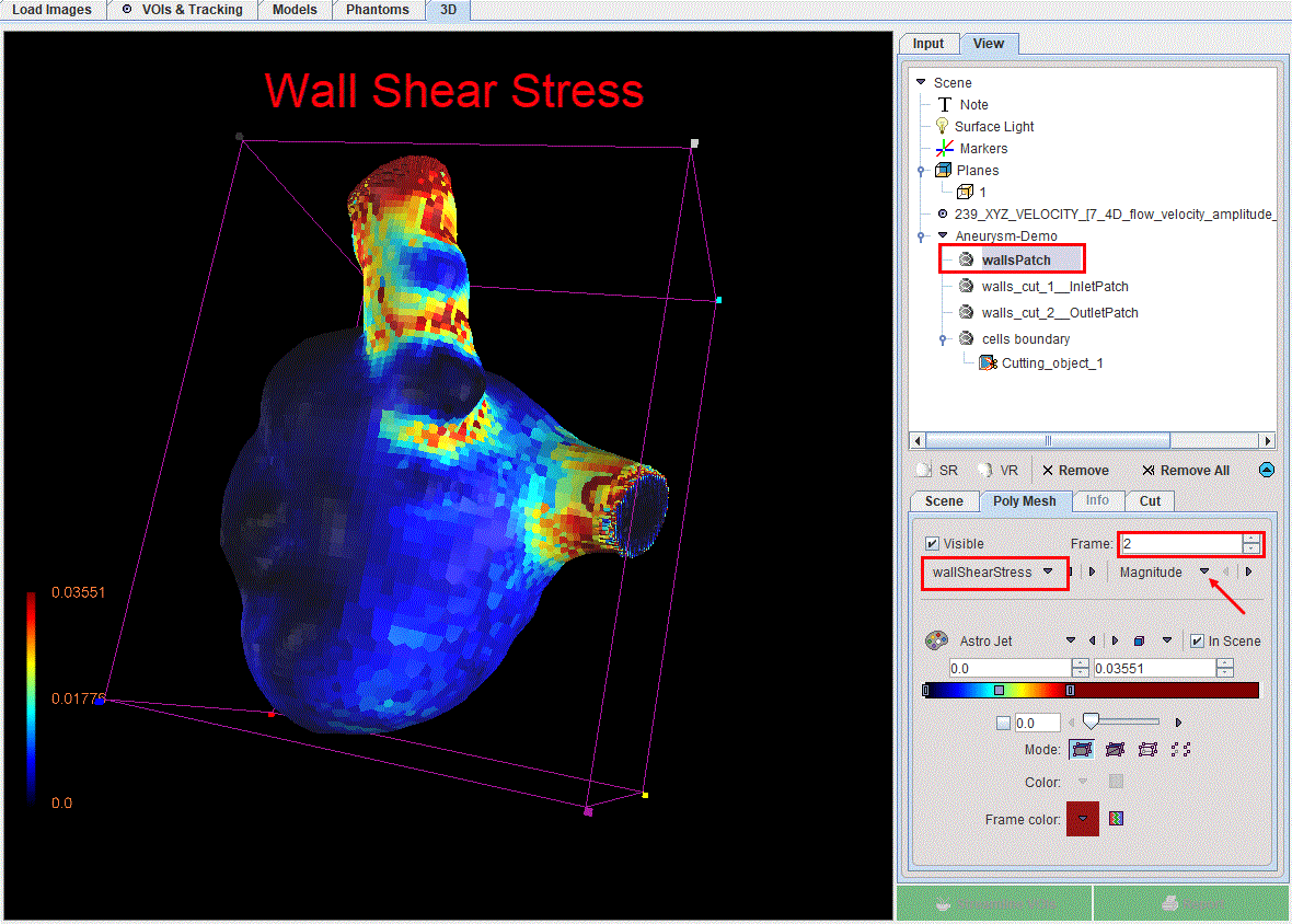
The wall shear stress maps can also be assessed in the 3D environment. For this purpose the wallsPatchVisible box is enabled and the wallShearStressMagnitudeFrame 2 selected as texture. The scene is updated as illustrated in the capture below:
Note: Please refer to the PMOD 3D Rendering Tool Users Guide for any further information about the cutting planes and texture of the scene.