In this step the boundary conditions are defined for the cutting planes and for the wall. There are two physical variables which characterize the fluid flow: the pressure and the velocity.
The Boundary Conditions interface is illustrated below:

The Internal field allows setting initial values for both physical variables. These values will be assigned to every cell in the volume mesh. It allows starting the simulation from field with non-zero values. In the example above the zero value is used both for the pressure and velocity in the CFD simulation.
The P (pressure) is a scalar and is defined as a kinematic pressure (pressure/fluid density) and measured in [m2/s2]. There are two types of pressure boundary conditions: fixed value and zero gradient. With the fixed value selection the value of the variable will stay as defined throughout the simulation. With the zero gradient selection it is assumed that there is no value gradient along the flow direction. Particularly, it is assumed that the flow is fully developed at this boundary, and the value will be calculated by the solver.
In the CFD simulation example above the zero gradient is set for the walls and the inlet_plane surfaces and a fixed value of 0 for the outlet_plane surface.
The U(velocity) is a vector and is measured in [m/s]. There are three types of velocity boundary conditions: fixed value, surface normal fixed value and zero gradient.
When the fixed value is set the value of the variable will stay as defined throughout the simulation. A similar situation is obtained with the surface normal fixed value selection but in this case the vector alignment is always normal to the surface for which the boundary condition is applied. The inflow is defined by a negative value. The outflow is defined as a positive value. The zero gradient significance is the same as for the pressure variable: assumes the flow is fully developed at this boundary, and the value will be calculated by the solver.
In the example above, the following settings are done for the U variable:
▪walls surface: fixed value0 0 0 (the so called no slip boundary condition)
▪inlet surface: surface normal fixed value with a value of -0.26
▪outlet surface: zero gradient
Note:
It is recommended NOT to set fixed constraints on the flow at one surface for both variables, e.g. pressure and velocity set as fixed values at the inlet.
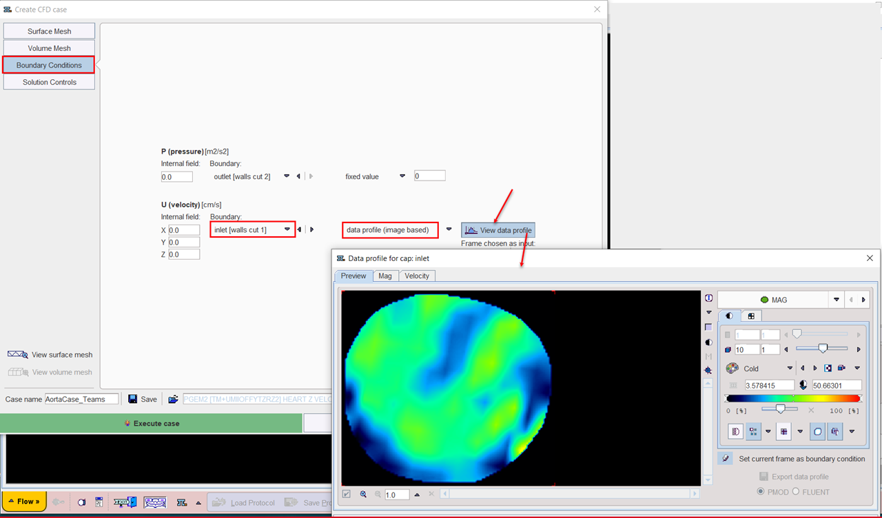
When velocity profiles were generated and set for a selected frame for a cutting plane in the 3D interface (e.g. inlet), these profiles are available for selection as data profile (image based) boundary condition for the velocity. The View data profile button allows visualizing these profiles as illustrated in the capture below.