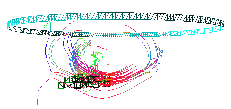
The 3D page initially shows the tracks together with the VOIs.
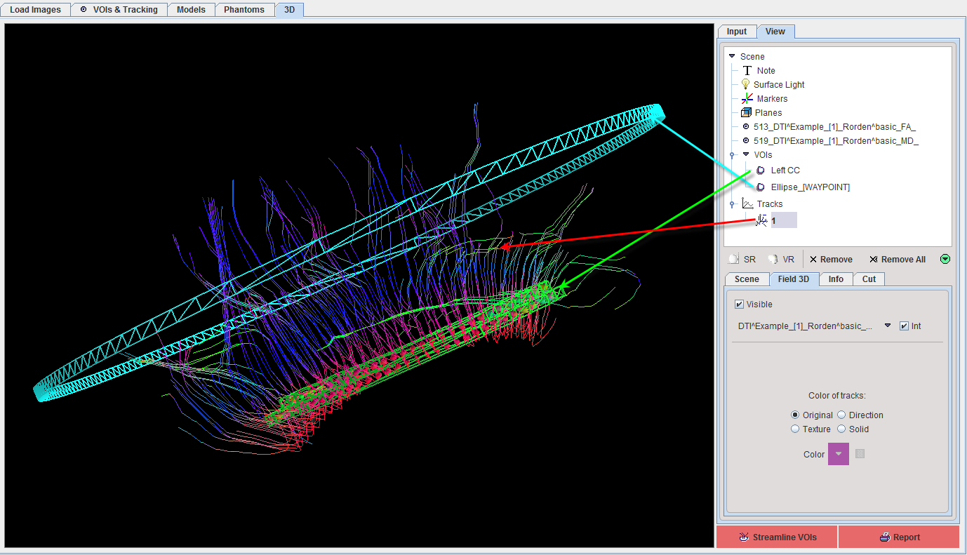
Note the elements in the Scene tree in the upper right. An objects can be selected in the tree its appearance changed in the lower part. Please refer to the PMOD 3D Tool Users Guide for details about the rendering.
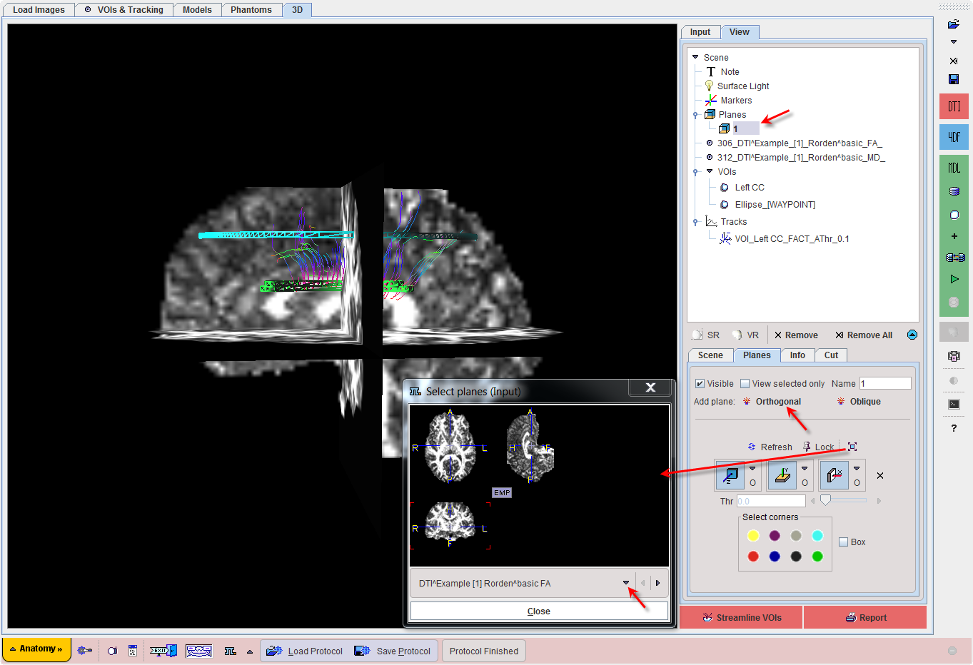
As an example, FA image planes can be added by clicking at Planes in the tree, activating the Orthogonal button for the Add planes, opening the planes locator and finally selecting the FA image.
Examples with Different VOI Settings
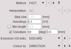
The two VOIs described above will be used for illustrating the effect of various settings on the resulting tracks. The left corpus callosum VOI used for seeding, and the tracking algorithm is configured by the setting below.
The following results are obtained when changing the role of the ellipse VOI.
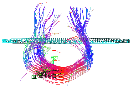
Ellipse: NEUTRAL VOI |
|
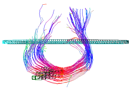
Ellipse: WAY VOI |
|
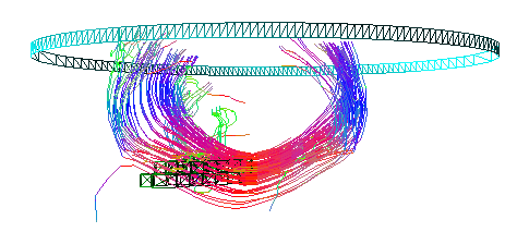
Ellipse: END VOI |
|
Ellipse: EXCLUDE VOI |
Using the ellipse VOI for clipping results in all tracks being shown but clipped at the level of the ellipse. |
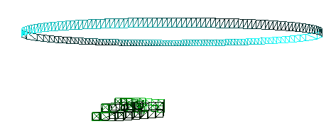
Ellipse: EXCLUDE VOI |
When discarding all tracks passing the ellipse only few tracks remain in the scene. |