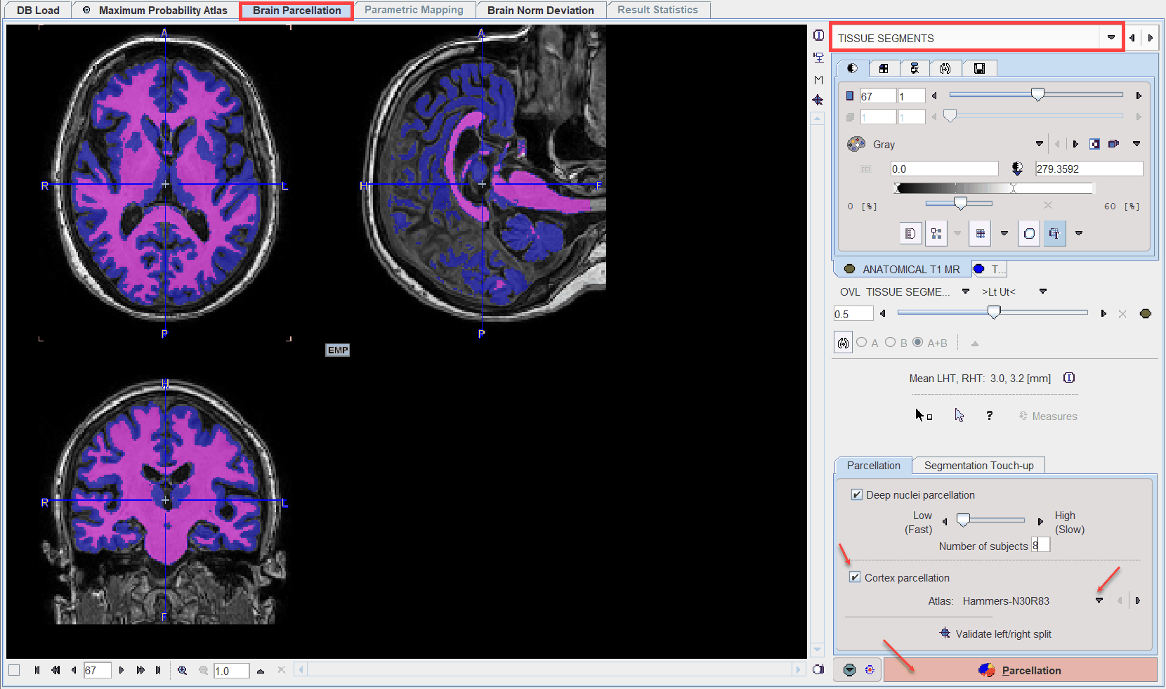
The result of the segmentation is shown as a fusion of the tissue segment map with the MR image on the TISSUE SEGMENTS page. Note that the TISSUE SEGMENTS image tab contains a label image with gray matter, white matter and CSF represented by the label values 1, 2 and 3, respectively. The segmentation can be trimmed using the controls in the Segmentation Touch-up panel as described above.
Landmark Definition
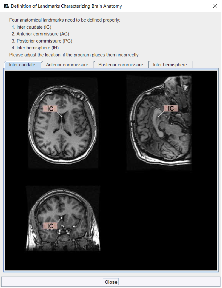
The parcellation procedure requires four anatomical landmarks:
▪an inter-caudate point (IC) for separating the ventricles,
▪the anterior commissure (AC),
▪the posterior commissure (PC)
▪an inter-hemispheric point (IHP) for defining the plane which divides the hemispheres.
A visual help for this task can be opened with the ? button to the left of the Indexes button. It appears with the IC landmark on front as illustrated below.
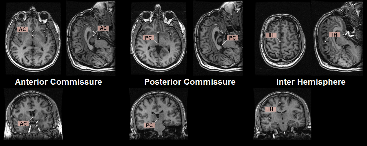
The location of the other three landmarks is illustrated below.
Estimates of the landmark locations are obtained as part of the segmentation. They can be inspected by activating the ![]() button, which also opens the markers panel. There theTraingulate list allows easily selecting any of the 4 landmarks, which is shown as a marker in the triangulated image. If the location is not accurate within a few millimeters, please adjust the position by dragging the marker. You may need to shift the fusion slider to the left in order to see the markers on top of only the MR.
button, which also opens the markers panel. There theTraingulate list allows easily selecting any of the 4 landmarks, which is shown as a marker in the triangulated image. If the location is not accurate within a few millimeters, please adjust the position by dragging the marker. You may need to shift the fusion slider to the left in order to see the markers on top of only the MR.
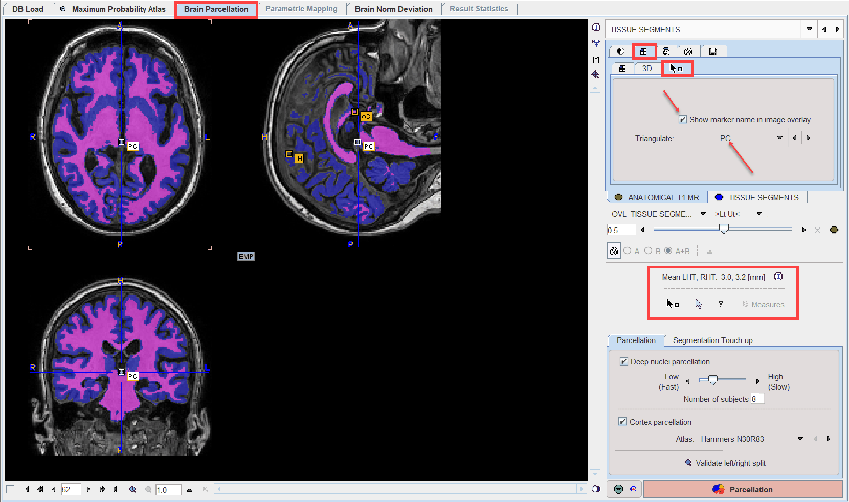
To avoid marker placement when clicking into the images for triangulation, hold down the SHIFT+CTRL keys. Note the indication of the landmark which needs to be placed (IC, AC, PC, IH) as part of the cursor symbol.
Brain Indexes
Based on the segmentation five indexes are calculated which will be further employed for the selection of the most similar hemispheres from the knowledge base:
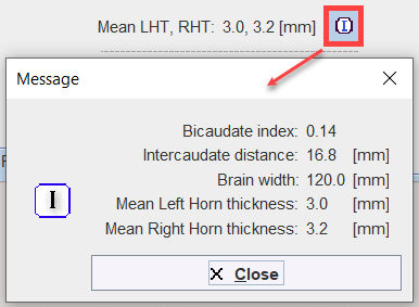
▪Bi-caudate index: ratio of caudate distance and brain width.
▪Intercaudate distance: minimal distance between the caudate heads in the axial plane.
▪Brain width: size of the brain in the left-right direction.
▪Left horn thickness (LHT): mean thickness of left horn in coronal section.
▪Right horn thickness (RHT): mean thickness of right horn in coronal section
The horn thicknesses are shown in the user interface, and complete information can be opened with the button indicated below.
Split Validation
The Validate left/rightsplit button opens a dialog window for inspecting the result of the brain splitting procedure.
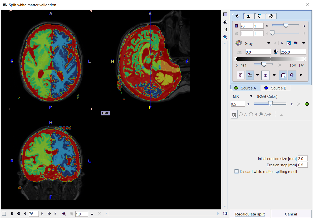
There are 7 resulting segments, which are shown in the Source B tab. They correspond to the left white matter, left gray matter, right white matter, right gray matter, cerebellar gray matter(including pons), cerebellar white matter and CSF. If the procedure doesn't come up with at reasonable splitting into right and left parts, there are two options to proceed. The Initial erosion size [mm] and Erosion step [mm] parameters can be modified and the procedure restarted using Recalculate split, or splitting can be switched off by the Discard white matter splitting result flag. In the latter case please confirm with the Discard split button to close the window.
Note: A successful brain splitting is mandatory for the brain parcellation approach. If it fails and adjustment of parameter settings cannot fix the problem, parcellation will not proceed any further.
Parcellation
Deep nuclei parcellation calculates the brain structure shapes based on the knowledge base and the segmented MR image. Each hemisphere is processed individually. The user may select the Number of subjects (<=26) which are taken into account during parcellation. A higher number tends to provide more accurate results, but 8 has been found to be the optimal compromise between speed and accuracy.
Cortex parcellation uses the grey matter segment and a transformed atlas to derive cortical VOIs. The VOI Atlas to be used can be selected in the list. Note that the atlas will be intersected with the GM segment for creating the cortical VOIs.
Calculation is started with the Parcellation button. Its duration highly depends on the system performance (RAM, processors) and the selected number of subjects, and can range from minutes to hours.